| Home > Reviews > Constraint Singularities | |
Constraint Singularities |
|
|
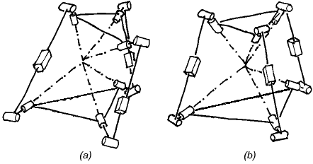
This report is a follow-up of the one explaining the puzzling singularity of a translational parallel manipulator built at Seoul National University. It examines the phenomenon of constraint singularity in a more general context. 1. IntroductionSince we published our paper on the singularity of the SNU parallel manipulator we have received a lot of feedback. Many people found the issue fascinating and sent us comments and questions. It became clear that the ability of 3-UPU translational manipulators to allow rotations in certain configurations has already been discovered by Di Gregorio and Parenti-Castelli [1,2]. The occurrence of the same phenomenon for a 3-PUU translational robot was studied by Matteo Zoppi in his Master's thesis in PMAR lab at the University of Genoa, completed in 2000. In the present paper, we will briefly comment on the results of [1] and [2]. Then, we will look in more depth into the nature of what we called constraint singularities and show that they represent a more general phenomenon which is not limited to the "rotational singularities" [1] of translational parallel robots. In [1] the authors observe that there exist configurations where a general 3-RRPRR translational robot may allow a fourth instantaneous DOF of the platform. They also list a few cases when this can occur. In their fine paper [2] Di Gregorio and Parenti-Castelli analyse the singularities of a general 3-UPU parallel mechanism assembled for translation, i.e., satisfying the conditions given by Tsai [3]. To do that, they start with the most general velocity equations of the mechanism, i.e., the expressions of the (angular and linear) velocity of the platform as linear functions of all joint velocities, active and passive and find the conditions for a non-zero end-effector instantaneous motion to be possible when the actuator velocities are all zero. After studying the linear system of equations, the authors observe that all conditions for a non-zero platform motion can be separated into conditions for either a redundant translation or an uncontrolled rotation of the end effector. They call the two groups of configurations, translational and rotational singularities, respectively. 2. The Importance of the Passive Joint VelocitiesThe first important observation that should be made is that the reason why Di Gregorio and Parenti-Castelli, unlike others, did not miss the rotational singularities was their use of the full velocity equations rather than only the input-output velocity equations, where the passive velocities are eliminated. The fact that the singularities of a mechanism with closed kinematic loops cannot be properly described and understood if only input-output equations are used was emphasised in [4], where singularities were defined and classified using the general velocity equation of an arbitrary mechanism. For some parallel mechanisms, a careful selection of the input-output equations allows comprehensive singularity analysis [5]. These are mechanisms where the mobility of the serial chain of each leg is the same as that of the mechanism as a whole (e.g., 6-DOF platforms, spherical and planar mechanisms, positioning mechanisms with only prismatic joints). However, for many parallel mechanisms with fewer than six DOFs this condition does not hold since each leg has more freedoms and fewer constraints than the platform – only the combination of the legs' constraints results in the desired mobility of the platform. It should be noted that, even for the mechanisms discussed in [5], there is one singularity type that cannot be described with the input-output equation alone. This is the singularity of type IIM (increased instantaneous mobility) also referred to as an uncertainty configuration by Hunt (for single-loop chains) [6]. In such configurations the mechanism as a whole gains an additional degree of freedom. Note that this phenomenon is obviously unrelated to the choice of the actuated joints or the end-effector in a kinematic chain. We will return to IIM singularities and their relationship with constraint singularities later. 3. The Importance of Geometrical InsightDi Gregorio and Parenti-Castelli correctly derive the condition for a rotational singularity of a 3-UPU mechanism, namely, the linear dependence of the three normal vectors to the U-joint planes in the three legs. To reach this geometrical result they apparently needed to calculate symbolically the determinant of the relevant Jacobian, an expression that takes half a page in their paper's Appendix. This amazing formula is, in a way, a perfect advertisement for the application of geometrical methods, such as screw theory, in robotics. Indeed, the result becomes almost obvious when reciprocal screws are used. The constraint wrench of each leg is a pure moment normal to the U-joint plane; the platform can rotate only when the constraint system of the platform does not contain all couples, i.e., when the three moments are linearly dependent. Moreover, with a knowledge of the basic screw systems it is easy to see which exactly are the acquired freedoms when the constraints do become singular. This is why one of the authors of the present paper was able to confidently describe the redundant instantaneous freedoms of the SNU robot at the breakfast table in Seoul on the following morning after the lab visit, and not even a paper napkin was needed for the proof. 4. Constraint Singularity is More Than Just Rotation SingularityIt is important to realize that the phenomenon of constraint singularity is more general and more fundamental than the ability of certain translational robots to rotate. To make this completely obvious, let us look at an example of a constraint singularity that can also be described as a translation singularity. Consider another 3-UPU robot but this time it is assembled not as a translational device but rather as a spherical wrist (Fig. 1). The design is such that all three R joint axes in the base have a common intersection point; the same is true for the three platform R joints; and, finally, these two points are made to coincide. This mechanism was first described in [7].
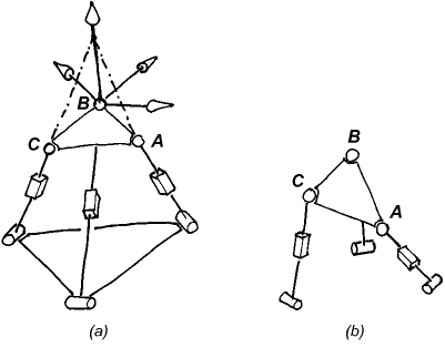
The constraint wrench for each leg is a pure force through the rotation centre parallel to the two R joints fixed in the leg. Normally, these three forces are linearly independent. The constraint system is then composed of all forces through the centre and hence the system of platform freedoms is the reciprocal screw system, namely, all rotations about the point O. Which explains why the mechanism is indeed rotational. However, if the three leg planes can intersect in a common line, as is the case in Fig. 1(b), the three forces become linearly dependent. Now the constraint system is only two-dimensional and its reciprocal system, that of the platform freedoms, becomes four-dimensional. And since the constraint system is a planar pencil of rotations, the platform freedom system is spanned by a translation normal to the plane of the pencil in addition to all the rotations through O. Thus, the end effector gains a translational degree of freedom. For this mechanism, the rotation singularities are the usual parallel singularities (Type 2) where no extra freedom is gained but one of the existing platform freedoms becomes uncontrollable. These singularities can also be found, without wasting napkins, with some screw-system observations, which we will leave as a non-trivial exercise for the reader. But before the reader can get on with the homework, we need to give an extra piece of data. That is, we "forgot" to mention which were the actuated joints. For our purposes, we will assume that the actuated joints are the revolute joints at the base. (This is feasible. Moreover it is not a very strange choice, especially if the prismatic joint is replaced with a (fifth) revolute parallel to the two revolutes fixed in the leg in Fig. 1. We will look at what happens when the prismatic joints are actuated later). The answer is that, for an RO (i.e., a parallel type, or Type 2) singularity to occur, the three planes of the upper U joints must intersect in a common line, i.e., they must have linearly dependent normal vectors. It is no accident that this is similar to the condition for the rotational singularities of the 3-UPU mechanism studied in [2]. The condition for the existence of an instantaneous self motion when the actuators of the robot in Fig. 1 are locked decomposes in two just as was the case in the Di Gregorio study. Indeed, the constraint system with the actuators locked is decomposed into two systems: a system of forces through the rotation centre; and a system of moments normal to the upper U joint planes. The two systems cannot intersect, so singularity occurs when one of them loses rank. In one case the platform has an uncontrollable rotation, in the other there is a translation unstoppable with the actuators. It is the translational singularity that is a constraint singularity, while the rotational one is of the plain parallel type. The fundamental difference between the two groups of singularities is not that the "gained" freedom is a rotation in one case and a translation in the other. Rather, the uncontrollable freedom is a truly new one at a constraint singularity, and one of the already present platform motions at a usual parallel singularity. To see more clearly that the rotation-translation division is beside the point, let us look at another mechanism, the 3-RPS parallel manipulator and two of its singular configurations.
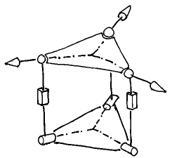
The configuration in Fig. 2(b) is an ordinary parallel singularity. The platform has one uncontrollable freedom, namely a rotation about the line BC, when the prismatic actuators are locked. In Fig. 2(a) we see another singular configuration. Here, the uncontrollable motion is again a rotation, with an axis passing through both point B and the intersection point of legs A and C. The second configuration is, in fact, a constraint singularity. Despite the apparent similarity, the two singularities are quite different. In Fig. 2(b) the constraint wrenches (forces through the S joints and parallel to the R joints) are linearly independent and the platform has three DOFs. In Fig. 2(a), however, the three constraint wrenches all pass through point B and lie in the platform plane, and hence form only a two-system. The platform gains a freedom and can instantaneously move with 4 DOFs. Indeed, it can rotate arbitrarily about point B and translate vertically. From a kinematic point of view these are completely different phenomena. In one case, the loss of control is due to the (so to speak) unfortunate choice of the actuators. If, in Fig. 2(b), you can actuate the base R joint rather than the P joint of leg B, you would have full control of the platform. In Fig. 2(a), there is no "fortunate" choice of three actuators that will prevent the platform from moving instantaneously. The distinction between the two types is important also because a constraint singularity, whether it is rotational or not, will generally fail to show up if you look only at the input-output equations of the manipulator. Finally, let us give another example of a constraint singularity of a 3-RPS robot (Fig. 3). This time, the platform is in a much more unperturbed pose than in Fig. 2(a), however, the three base R joints need to intersect in a point.
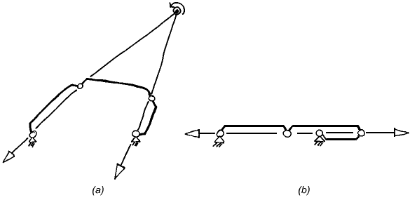
5. Constraint Singularities are a Subset of IIM SingularitiesIt is now clear from the discussion in Section 4 that constraint singularities are in fact IIM singularities. Indeed assuming that the mechanism is non-redundant, its full-cycle mobility is equal to the mobility of the end-effector. If, at a certain configuration, the platform gains a degree of freedom the instantaneous mobility of the whole mechanism must have instantaneously increased as well. As we mentioned in the Introduction, it was remarked in [1] that the translational parallel robot gains a fourth DOF in a rotational singularity. Yet, not every IIM configuration is a constraint singularity since it is possible for the mechanism to gain a freedom while the DOF of the end-effector remains unchanged. To illustrate this and simultaneously provide what must be the simplest example of a constraint singularity, let us consider the four-bar linkage in Fig. 4. Assume that the link lengths are such that the mechanism can become flattened, Fig. 4(b). In the shown configuration, the kinematic chain as a whole acquires an instantaneous mobility of two. Usually the output link of a four bar is one of the rotors and, therefore, the end-effector will always remain with at most one DOF, including in Fig. 4(b).
However, let us assume that the output link is the coupler, a kind of "platform" of a 1-DOF planar "parallel manipulator" with two RR legs, one of which is passive. Now, in the singularity of Fig. 4(b) the end-effector gains a freedom and has two instantaneous DOFs. Indeed, it can now rotate about any point on the line containing all joint centres and, of course, translate in the normal direction. (Note that this singularity adds both new rotations and a new translation to the platform freedoms. Is it a rotational or a translational singularity?) To see that this is a constraint singularity like the ones already described, observe that each RR leg imposes one planar constraint on the platform: a force through the two joint centres of the leg. Normally, these two lines are distinct and span a 2-system. The planar component of the reciprocal system is the 1-DOF system of the coupler freedoms. When the lines of the two constraint forces intersect, the freedoms are the rotations about the intersection point, Fig 4(a). When the two lines are parallel the coupler must instantaneously translate in the normal direction. However, in Fig. 4(b) the constraints become one, more precisely they are linearly dependent and span only a one system. The system of output motions then becomes the 2-system which we already described. Extra Freedoms and Uncontrollable FreedomsWe saw that at a constraint singularity the platform acquires additional DOFs. Then, obviously, not all of the output freedoms can be controlled. However this does not mean that it is always a new degree of freedom (i.e., one that exists due to the constraint singularity) that will be uncontrollable. More precisely, the redundant end-effector motion present when the actuators are locked may be inside the screw system of platform freedoms which exist at a non-singular configuration. For example, let us look again at the mechanism in Fig. 1(a), but this time, let us assume that the prismatic joints are actuated. In the configuration shown in Fig. 1(b), as we pointed out, there is a constraint singularity and the platform gains a translational DOF. Yet, when the prismatic actuators are locked the end-effector cannot translate. The only instantaneously possible motion is a rotation about a vertical axis through the centre. The translation of the platform can be achieved but only if the actuators can move. It should be noted that while the system of uncontrollable freedoms or redundant end-effector motions is well defined, a system of "controllable freedoms" cannot be specified in a unique way. Indeed the redundant freedoms of the platform are the motions possible when the actuators are locked. It is useful to define a screw system as controllable if it has a zero intersection with the uncontrollable system and together with it spans the whole system of possible platform motions. Note that we cannot ensure that the output twist is restricted to such a system, due to the possible presence of transversal redundant motion (so, practically speaking, we do not have full control). For example, assuming prismatic actuators in Fig. 1(b), the system spanned by the horizontal rotations through the centre and the vertical translation is controllable, in the defined sense. Yet we cannot prescribe a motion in that system and enforce it since we cannot prevent the platform to also rotate about the vertical axis. In a 3-UPU translational mechanism at a rotational constraint singularity we will say that the system of platform translations is controllable, although we cannot actually control the linear velocity of all points of the body. In the two examples the mentioned controllable systems are not unique. In fact, any motion that is not a RO motion can be part of a controllable system. This understanding on the meaning of the terms controllable and uncontrollable, when referring to the possible platform motions will allow us to make a clear distinctions between the two constraint singularities illustrated by Fig 1(b) (for the two different choices of the actuated joints). In both cases we have a redundant motion of the platform, but only in one case we can say that we have a redundant output motion. That is so since for a rotational device, which the mechanism is intended to be, the output motion is not the motion of the platform in general, but rather the rotation of the platform. Hence, In one case, when the actuators are prismatic, we have a constraint singularity that leads to redundant output, i.e., one of the desired rotational freedoms is uncontrollable. In the other case, when the first revolute joints are the active ones, the output rotations are a controllable system. Therefore, rigorously speaking, there is no redundant output motion, and the uncontrollable translation of the platform can be thought of as a redundant passive motion. Similarly, in the rotational singularities of translational robots we should not speak of the uncontrollable rotation as a redundant output motion, since rotations were never intended as output, but rather as an instantaneous passive motion in the mechanism. ConclusionA constraint singularity is a configuration of a parallel mechanism with a DOF of the platform, n, lower than the number of joints in any leg. At such a singularity, the system of the constraint wrenches degenerates and becomes a screw system with a dimension lower than 6-n. As a result, the system of output freedoms instantaneously increases its dimension. At a such a configuration, both the mechanism as a whole and the platform have at least n + 1 DOFs. The extra degree(s) of freedom of the platform may or may not be controllable by the actuators. Bibliography
|
|
Home |
Bibliography |
Patents |
Terminology |
Reviews |
Software |
Who's Who |
News Site Map | Site Search | Contact Us | About Us |
| Copyright © 2000– by Ilian Bonev | Published on: July 5, 2001 |


