| Home > Reviews > Kanuk Parallel Robot: A 4 DOF Robot for Material Handling | |
Kanuk Parallel Robot: A 4 DOF Robot for Material Handling |
|
|
It is in the middle 90's, in the footsteps of the Delta robot success, Mr. Clavel asked Mr. Rolland to investigate new parallel robot designs in order to acheive tdisplacement with the three translations and one or two useful rotations. The designs had to be applicable to industry as low-cost material handling manipulators. The specification criteria were very high throughput and simple construction. If possible, the design had to find innovative means to increase workspace, somewhat limited in parallel manipulators. Mr. Rolland came out with the idea to focus on one rotation at first, thus on 4 DOF manipulators, and proposed the Kanuk architecture. This robot is 4 DOF quadrapod also using the parallelogram principle in order to eliminate rotations.
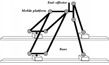
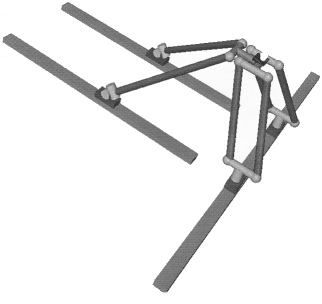
The DesignThe Kanuk manipulator features three main kinematics chains. It allows displacement along three independent axes and a rotation which is tilting the mobile platfiorm sideways. The basic idea behind the Kanuk robot design is not far from the Delta robot design itself since it is again making use of parallelogram kinematic chains. Each parallel bar is maintained together by two stiff springs. Two of the kinematic chains are made of a single bar along which are cables are set for platform rotation transmission.
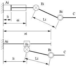
In order to increase workspace, the manipulator structure makes use of linear axes which include the actuators and sensors. They can either be in parallel or perpendicular layout. Any other linear actuator layout can also lead to possible configurations. These actuators can be linear motors, rack and chariots as shown on the following schematic, cylinders, etc. The parallel axis layout brings the unlimited workspace potential which can be used in warehouses, for example. The main linear actuator disadvantage is acceleration which is somewhat limited by technology since the commercially available axes are limited to 5 G's. Usually, the parallel axis layout can be simplified by having two chariots (one for a parallel bar and one for a single bar) sharing one linear track.
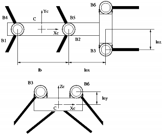
The use of base-mounted actuators and low-mass links allows the mobile platform to achieve accelerations of up to 5 G's in experimental environments. This could be further improved if stiffer structures are built or linear motors are used. The mobile platform has been built with passive paltform joints, concentrated in order to keep the structure as stiff as possible by respecting the triangular transeversal configuration made by the facing parallel bars. Inasmuch, the mobile platform has to have the two single bars to be located as far apart as possible so that smaller forces may be used to maintain platform position.
The performance of the Kanuk robot makes it a perfect candidate for high-throughput pick and place operations for applications such as media (CD, DVD, cassette) changer, material handling in heavy payload conditions and wharehouse operations. Bibliography
Related Links
|
|
Home |
Bibliography |
Patents |
Terminology |
Reviews |
Software |
Who's Who |
News Site Map | Site Search | Contact Us | About Us |
| Copyright © 2000– by Ilian Bonev | Published on: July 15, 2001 |


