| Home > Reviews > Orthoglide: A 3-Axis Parallel Machine Tool for High-Speed Machining | |
Orthoglide: A 3-Axis Parallel Machine Tool for High-Speed Machining |
|
IntroductionMost industrial machine tools have a serial kinematic architecture. It means that each axis supports the following one, including its actuators and joints. High Speed Machining (HSM) highlights some drawbacks of such architectures: heavy moving parts require high stiffness from the machine structure to limit bending problems that lower the machine accuracy, and limit the dynamic performances of the feed axes. Parallel Kinematic Machines (PKMs) attract more and more researchers and companies, because they are claimed to offer several advantages over their serial counterparts, like high structural rigidity and high dynamic capacities. Indeed, the parallel kinematic arrangement of the links provides higher stiffness and lower moving masses that reduce inertia effects. Thus, PKMs have better dynamic performances, which is attractive for HSM. However, most existing PKMs have a complex geometrical workspace shape and highly nonlinear input /output relations. For most PKMs, the Jacobian matrix, which relates the joint velocities to the output velocities, is not constant. Consequently, the performances may vary significantly for different points in the workspace and for different directions at one given point, which is a serious drawback for machining applications. To satisfy the needs of machining applications, a parallel kinematic architecture should preserve good workspace properties such as regular shape and homogeneous kinetostatic performances throughout. A parallel kinematic architecture for HSM should also respect some technological constraints:
The Orthoglide project aims at building a small-scale prototype of a parallel kinematic machine tool for HSM with a kinematic behaviour close to the one of a classical serial 3-axis machine. Description of the OrthoglideThe kinematic architecture chosen for the Orthoglide is presented on Fig. 1. It has variable foot points and fixed-length struts. This machine has three parallel PRPaR identical chains (where P, R and Pa stand respectively for prismatic, revolute, and parallelogram joints). The actuated joints are the three orthogonal prismatic ones. The output body is connected to the prismatic joints through a set of three parallelograms, so that it can move only in translation (note that two parallelograms are sufficient). Also, the Orthoglide is free of singularities and self-collisions, which makes it fully available for various tool paths. The full theoretical kinematic analysis of the Orthoglide is described in [Wenger and Chablat, 2000].
The parallel architecture respects the above-mentioned design constraints, but it also features one more interesting characteristic–the shape of its workspace is close to a cube (Fig. 2).
Kinematic and Geometric Design of the OrthoglideThe Orthoglide has been designed so that it has an isotropic configuration in its workspace. This configuration is reached when the orientation between the AiBi axis (Fig. 1) of the linear joint and the axis BiCi of the parallelogram is the same for each leg, and when all parallelograms are orthogonal to each other (Fig. 2). To have a kinematic behaviour close to the one of a serial 3-axis machine tool, we also impose that, in this configuration, the velocity transmission factors are equal to 1. This condition implies that for each leg, the axis AiBi of the linear joint and the axis BiCi of the parallelogram are collinear. Since at the isotropic configuration, the vectors BiCi are orthogonal, this implies that the vectors AiBi are also orthogonal, i.e., the linear joints are orthogonal (Fig. 2). The PrototypeA design methodology has been provided to determine the dimensions of the Orthoglide for a prescribed cubic Cartesian workspace with bounded transmission factors throughout. Following this methodology, the dimensions of the Orthoglide prototype have been calculated for a 200×200×200 mm prescribed Cartesian workspace and so that the velocity amplification factors remain between 0.5 and 2 throughout the workspace. The resulting dimensions are 310 mm for the length of the legs and 257 mm for the stroke of the prismatic joints (Fig. 3).
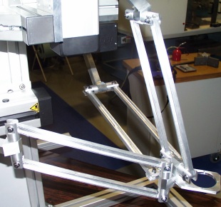
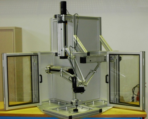
The ratio between the size of the prescribed cubic workspace and the joint range is r = 200/257 = 0.78. This result confirms the good compactness of the orthogonal arrangement of the prismatic joints. The result was already observed with the 2-DOF version of the Orthoglide [Chablat and Wenger, 2000; Wenger et al., 2001]. Note that this ratio is increased if the boundaries on velocity transmission factors are enlarged (1/3 and 3, instead of 1/2 and 2 for instance). The actuators are made of ball screws driven by rotary motors. The use of linear motors is also possible in the future. The motors have been chosen for a tool velocity of 1.2 m/s and an acceleration of 20 m/s² at the isotropic configuration. A dynamic model of the Orthoglide is currently being developed at IRCCyN and will be implemented on a D-Space card to control the machine. Real-time data acquisitions are also achievable with this system. Experiments will be conducted through the machining of plastic parts. Figure 4 shows the CAD model of the prototype and Figs. 5 and 6 show the actual prototype.
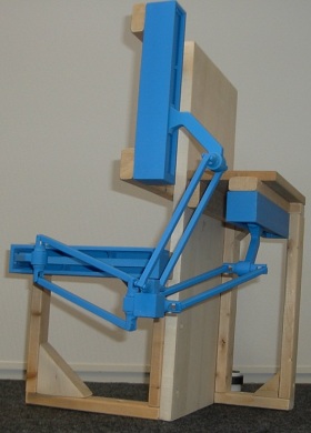
In addition to the actual prototype, small plastic mode of the Orthoglide mechanism was built at the Robotics Laboratory at Laval University, Quebec City (Fig. 7).
Further DevelopmentsStiffness analyses with Mecano (a finite elements software) are under way at Liège University (Belgium). The results will lead to a structural optimization of the Orthoglide by comparing experimental results to software simulations. Static and dynamic balancing conditions will be studied as part of a research collaboration between IRCCyN and Laval University in Quebec City. A 5-axis version of the Orthoglide is also under investigations. Bibliography
Related Links
|
|
Home |
Bibliography |
Patents |
Terminology |
Reviews |
Software |
Who's Who |
News Site Map | Site Search | Contact Us | About Us |
| Copyright © 2000– by Ilian Bonev | Published on: April 8, 2002 |