| Home > Reviews > Low-Inertia Parallel-Kinematics Systems for Submicron Alignment and Handling | |
Low-Inertia Parallel-Kinematics Systems for Submicron Alignment and Handling |
|
|
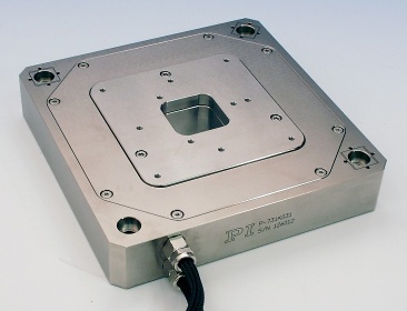
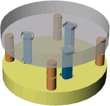
Editor's Note: This article presents the numerous parallel kinematics systems manufactured by Physik Instrumente (PI). PI is a leading supplier of micro- and nanopositioning systems and, by far, the most important industrial advocate of parallel mechanisms. IntroductionHexapod structures or Stewart platforms have long been used in flight simulators to provide rapid multi-axis motion. Similar systems have also recently appeared in theme parks to simulate roller coasters, race cars, dinosaur rides etc. Key to deceiving the senses of the human pilot or rider is being able to move and accelerate quickly in up to six degrees of freedom. While the above applications require long travel ranges rather than accurate motion, machining research has focussed on relatively large hexapod structures with significantly higher positioning precision. Hexapods for CNC machining have been around for quite some time now, but only a few systems have made it from the research centers and labs to tough production environments for reasons (among them low customer acceptance) not to be discussed here. At the other end of the scale, however, in ultra-precision, multi-axis positioning and alignment applications, hexapods are the accepted state-of-the-art. This article describes designs and applications of parallel-kinematics structures for the micro- and nanopositioning realm in applications from surgery to scanning microscopy and fiber alignment. Monolithic Parallel-Kinematics Structures with sub-nanometer PrecisionBefore Physik Instrumente (PI) started designing submicron precision hexapods more than a decade ago, PI designers had already gathered experience with different parallel-kinematics structures for sub-nanometer precision applications. Figure 1 shows the basic principle of a monolithic 3 degree-of-freedom (DOF) parallel kinematics nanopositioning stage with PZT drives and wire-EDM-cut flexures, similar to the models P-733 and P-527.RCD. This monolithic design is in contrast to the conventional serial kinematics design shown in Fig. 2. One of the products from PI's sub-nanometer series based on the monolithic principle is shown in Fig. 3.
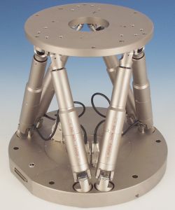
In high-speed nanopositioning applications, one advantage of the parallel-kinematics approach over the stacked or nested serial kinematics systems is the ultra-low inertia resulting in higher resonant frequencies, faster step response and higher scanning rates. Another advantage is active trajectory control on a sub-nanometer scale, which is possible when direct output metrology capacitive position sensors are integrated. Since each position sensor monitors the common platform, the smallest axis crosstalk effects are detected and can be compensated for in real time. This results in higher linearity and straighter scanning lines. Systems like these are used for example in ultra-high-resolution scanning microscopy and in semiconductor mask alignment and metrology applications, where sub-nanometer resolution and sub-millisecond response times are required. Tripod Parallel-Kinematics Steering Mirrors and Hexapods for AstronomyPI's first hexapods were developed for other applications. Ideas and designs had long been kicked around in PI's R&D department when the project took a new turn due to a request from the astronomy community. By the 80's PI had started development of high-speed, piezo-driven steering mirrors (mostly parallel-kinematics designs, see Fig. 4) for image stabilization purposes in astronomical telescopes. In the early 90's the NASA Infrared Telescope Facility (IRTF) on Mauna Kea, Hawaii, requested a new system that would stabilize the 210 mm diameter secondary mirror in real time and also align it in five degrees of freedom relative to the primary mirror (Theta-Z is not required with rotationally symmetric mirrors). Moreover, the positioning system needed to be able to operate in any orientation, be low profile, have a clear aperture, provide a high resonant frequency (for vibration suppression), and offer micron- and micro-radian-level precision. The motion range was ±10 mm in Z, ±3 mm in X and Y and ±2° for both rotations.
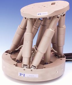
PI's solution was a micro-hexapod (Fig. 5). Two basic configurations were considered: both the variable-strut-length and the constant-strut-length designs were evaluated. Variable-Length-Strut HexapodsWith the variable-strut-length design, the strut length changes during a movement (like most classic hexapods). The advantage of this design is that the out-of-plane motion of the drives only causes a second order position error. With the constant-strut-length design the strut is a passive component, and is moved as one part. The pros and cons of this design are explained later. For the requirements of the astronomy application, the variable-strut-length design with U-joints (flexures provide higher precision but can limit the travel range) was chosen: In variable-strut-length hexapods, each of the 6 struts actively provides one DOF (the variable length) and also allows motion of the other 5 DOFs. Two U-joints per strut allow four degrees of freedom. A fifth DOF is contributed by the rotation between the screw and the nut in the strut. In this case, no additional rotary bearing is needed. The advantage is a stiffer system and further reduced friction and hysteresis. Some designs use linear encoders for each strut. They require the additional rotary bearing (because top and bottom end of the strut must not rotate with respect to each other) and the advantage of the direct encoder is compromised by this additional error source. Since the linear encoder does not see any of the errors contributed by the U-joints and rotary bearings, the accuracy and repeatability of the system still largely depends on the quality and tolerances of these components and on the control algorithms taking the special geometry into account. For the above-mentioned reasons, a very stiff, backlash-free screw and precision laser rotary encoder were used to control the strut length. To maintain the accuracy and resolution of the system, PI had to develop special high-stiffness, low-friction, backlash-free U-joints. During the design and testing phase, CAD, FEA (Finite Element Analysis) modeling, laser interferometry and laser vibrometry were employed to ensure that all requirements were met. Along with the mechanics and the control algorithms modeling the special geometry of the system, a new controller was developed to provide the user with high-level multi-axis motion commands. Another capability crucial for all alignment applications was the software-adjustable virtual pivot point.
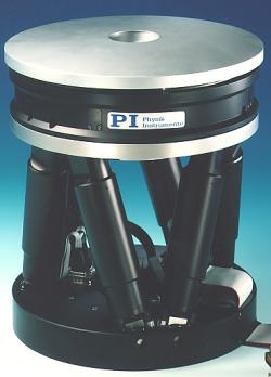
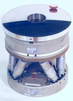
Soon after the development of the IRTF system, a similar image stabilization system and hexapod unit with a larger base (320 mm vs. 210 mm) was developed for the United Kingdom Infrared Telescope (UKIRT) on Mauna Kea, Hawaii (Fig. 6). Based on the experience gained in both projects, the M-800 Hexapod was released as a standard PI product in 1994. It also won the Photonics Circle of Excellence Award for that year. With a 200 kg load capacity and submicron resolution, the M-800 set new standards for compact multi-axis micropositioning systems. The hexapod was available in two versions, one of which in shown in Fig. 7. The main characteristics of both hexapods are presented in Table 1. Table 1: Basic specifications for the two versions of the M-800 hexapod.
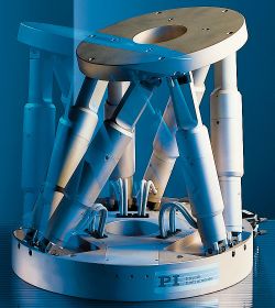
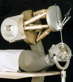
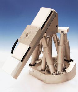
Applications of the M-800 hexapod were mainly aligning optics, but even for experiments in wind tunnels the design of the hexapod proved to be superior. Progress did not stop here and soon the M-800 was replaced with the further improved M-850 system (Fig. 8). In the mid 1990's a totally new application came from the medical field. The Fraunhofer Institute for Manufacturing Engineering and Automation (IPA), approached PI with the idea of a surgical robot. The M-850 was chosen because its motion versatility comes very close to matching the way a surgeon moves his hand. The difference is that the hexapod can be programmed to suppress any jitter and travel can be limited to predefined safe ranges.
Later this system was taken a step further and customized to better meet the specific requirements of the application and comply with the stringent medical safety standards. Figure 10 shows the Nonapod, a hexapod with three additional legs containing redundant position sensors. A seventh axis was added to increase the linear travel range (Fig. 11).
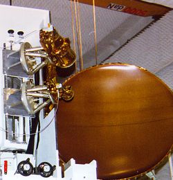
Another hexapod was designed for a satellite dish reflector and a feed alignment application. The hexapod's capability to pivot around any point in space was crucial for this application (Figs. 12 and 13).
Recently, several other hexapods have been developed for custom and standard applications. The latest models are the M-840 (Fig. 14), a lower-cost version of the successful M-850, and another custom design for the Atakama Large Millimeter Array (ALMA) telescope. ALMA, a joint project of the European Southern Observatory (ESO) and the US National Science Foundation (NSF), is aimed to become the world's highest-elevation full-time observatory, to be situated in the Atakama Desert in Chile. With 64 twelve-meter antennas spread out over an area 10 kilometers in diameter, ALMA will produce the highest resolution images of distant stars. The ALMA-hexapod had to be much larger than the M-850, with a large 395mm clear aperture. Due to the extreme operating conditions, it also had to be made water resistant (Fig. 15).
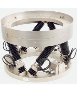
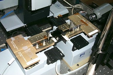
Constant-Strut-Length Hexapods for Photonics AlignmentWhile most of the above applications require relatively large forces as well as load capacities of up to several hundred kilograms, the alignment of MEMS and photonic components requires much higher precision instead. After having developed a number of serial-kinematics fiber alignment systems in the 80's and early 90's, engineers at PI realized that applications in this market were also perfect for hexapods, provided multi-axis repeatability of 100 nm and even higher resolution could be obtained. In photonics alignment positioning, ranges are very small. The parts to be aligned are very light-weight: fibers, waveguides, arrayed components, laser diodes, etc. While conventional alignment systems continued to be based on stacks of linear and rotary stages, with motors being bigger and bigger as approaching the base (to overcome the weight increase), PI engineers had found in the hexapod a solution to overcome the limitations of these stacked designs (accumulation of guiding errors, very high inertia causing long settling times, cable management issues with up to five moving cables causing friction and reducing accuracy and repeatability, thermal stability problems caused by the large amount of electrical drive energy required to achieve decent acceleration and deceleration with the heavy systems). The low-inertia approach of the hexapod design is an ideal match for photonics alignment. Straight-line speed is not an issue, because linear motion is basically non existent when it comes to aligning areas that are measured in square microns. Fast response and short settling times is what counts. This is best achieved with a stiff, low-inertia positioning system. Moreover, many applications (such as collimator or array alignment, see Fig. 18) require rotations around a user-specified pivot point. Serial kinematics systems operate with fixed-radius rotation stages, or goniometers. With hexapods, the pivot point is fully virtualized, a product of the parallel kinematics design and control algorithms. Furthermore, there are no moving cables, significantly reducing friction, complexity and the chance of connector failures. Compact size is another great advantage facilitating integration of the alignment engine into an automated packaging station. All the requirements were met by a new, constant-strut-length hexapod. The basic principle is shown in Fig. 16, while the actual structure of the PI design is represented in Fig. 17. Two photonics hexapods in an actual alignment application are shown in Fig. 18.
The novel photonics alignment hexapod was equipped with six high-resolution linear drives mounted on the base and moving perpendicular to the base plate. Six ultra-lightweight, constant-length struts and twelve zero-friction flexure joints were employed to connect the linear drives to the moving platform. Advantages of this design are:
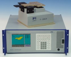
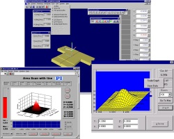
Along with the mechanics, a new controller (Fig. 19) with a built-in optical power meter and high-level scan and align routines (Fig. 20) was specifically developed to address the requirements of the photonics market.
Part of the system's mechanical performance depends on the design of the zero-friction flexures. FEA modeling and extensive testing helped PI's engineers to find an optimal solution that combines long motion range, ultra-high stiffness and insensitivity to stress and fatigue. Final RemarksLow-inertia hexapod structures are ideal multi-axis positioning and alignment systems. When designed and manufactured properly, systems with ultra-high precision and excellent dynamic properties result to solve the micro- and nano-alignment challenges in fields from astronomy to photonics alignment, nanotechnology and micromanufacturing. The shortcomings of high-inertia serial kinematics systems no longer limit the progress in these areas. Hexapods have been accepted by the photonics and optics markets. This fact was obvious at this year's OFC exhibition in Anaheim, CA. In the near future, expect to see a variety of improved designs, customized for high-tech applications around the world. Further Reading
|
|
Home |
Bibliography |
Patents |
Terminology |
Reviews |
Software |
Who's Who |
News Site Map | Site Search | Contact Us | About Us |
| Copyright © 2000– by Ilian Bonev and Polytec PI, Inc. | Published on: September 5, 2002 |